Alignment
Tomviz supports two types of data: volumes and tilt series. Volumes are from
tomographic reconstructions or sectioning, and tilt series are projection images
with associated angles. Specialized tools are provided for each type of data -
Data Transforms and Segmentation menus have tools for volumes, while the
Tomography menu provides tools for tilt series. Users can also add their own
tools via Custom Transforms.
Tilt Series
The Tomviz installer bundles a sample tilt series and the corresponding reconstruction. The tilt series sample will automatically set the tilt angles.
Loading sample tilt series
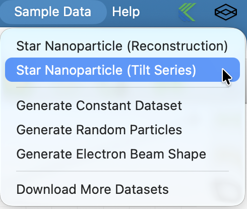
To load the sample tilt series select Star Nanoparticle (Tilt Series) from
the Sample Data menu.
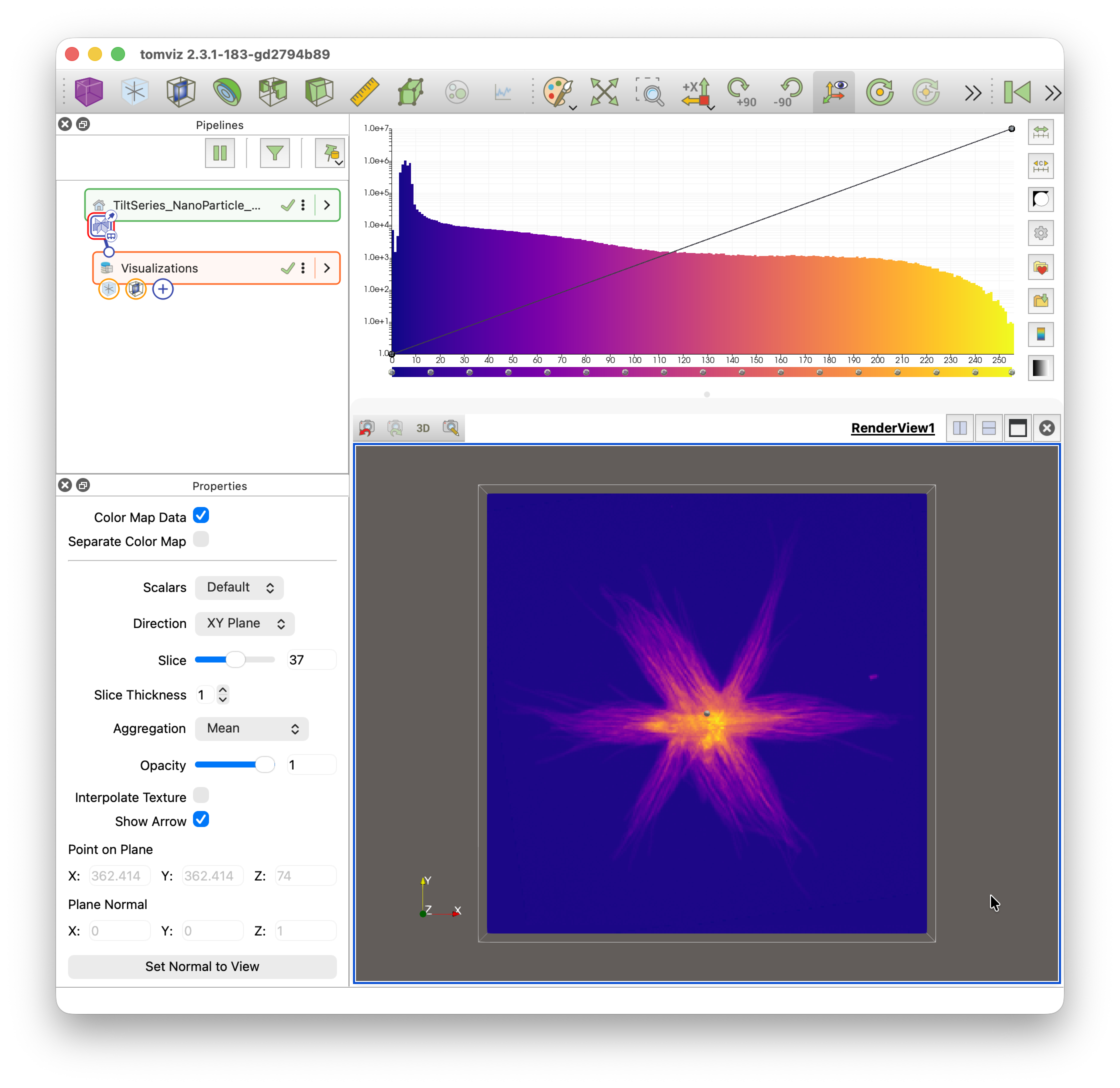
Once loaded you will see a default view of the data showing the outline and a slice through the center of the tilt series.
Creating a tilt series
This sample is loaded from an EMD file that already identifies it as a tilt series and stores the tilt angles. Data loaded another way, such as from a stack of TIFF files, must be manually marked as a tilt series and have its angles set.
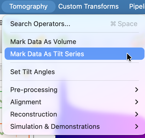
Data can be marked as a tilt series by selecting Mark Data As Tilt Series
from the Tomography menu. Tilt angles can then
be set by selecting Set Tilt Angles from the Tomography menu, which adds
a Set Tilt Angles transform to the pipeline.
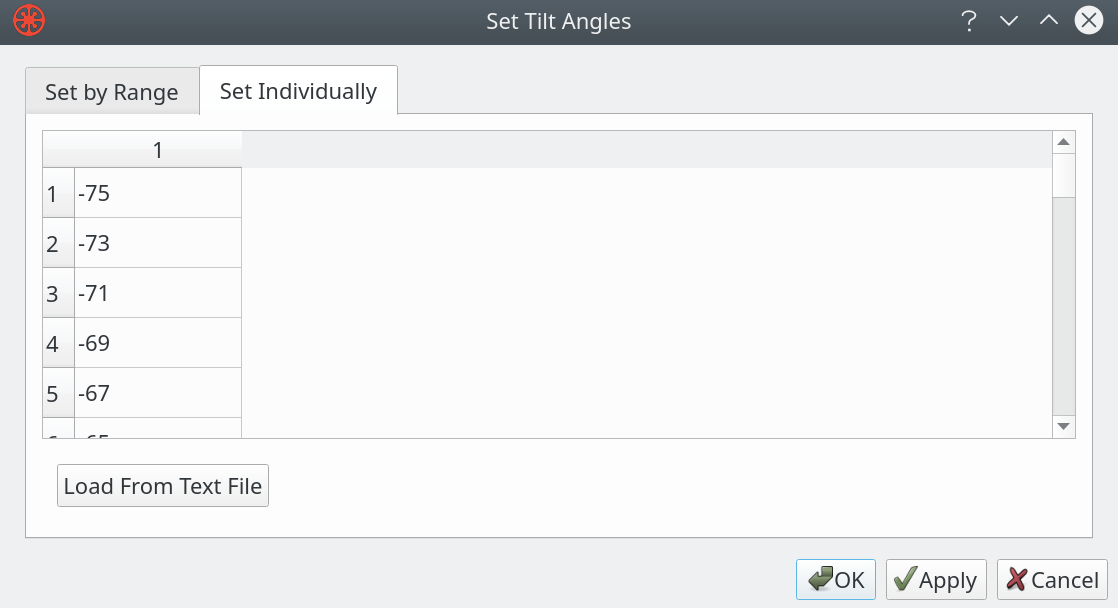
The angles can be specified in a number of ways, such as specifying the start and end image number with the start and end angles. It is important to enter accurate angles in order to obtain a good reconstruction.
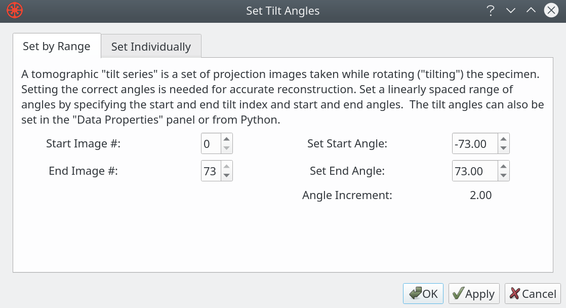
You can also set the angle for each image by choosing Set Individually from
the dialog. That mode supports loading a list of angles from a file too.
Aligning Data
The key to a good reconstruction is well aligned data. The Tomography >
Alignment submenu offers a number of automated and manual alignment options:
Image Alignment (Auto: Cross Correlation)
Image Alignment (Auto: Center of Mass)
Image Alignment (Auto: PyStackReg)
Image Alignment (Manual)
Tilt Axis Rotation Alignment (Auto)
Tilt Axis Shift Alignment (Auto)
Tilt Axis Alignment (Manual)
Shift Rotation Center (Manual)
Image data alignment
Image alignment can be achieved with automated algorithms - cross-correlation,
center-of-mass, and PyStackReg-based alignments are available. These are
found under Tomography > Alignment.
It is often necessary to use manual alignment methods as a final step to achieve the best alignment of projection images. The alignment offsets can be saved to a state file and adjusted in future sessions.
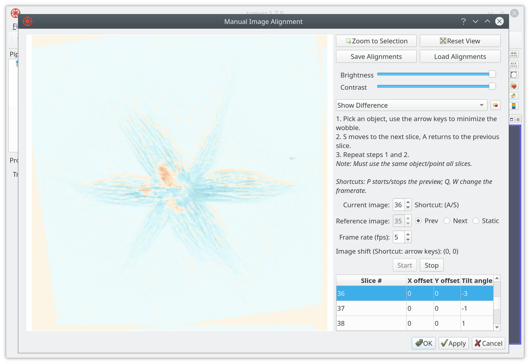
The manual alignment procedure uses two main interaction modes: toggling between images or showing a difference between two images. Ideally your sample will have a fiducial marker that can be used across all images for alignment. The current image can be aligned to the previous, next or a fixed image. The tool supports keyboard shortcuts to move between frames, introduce offsets, etc.
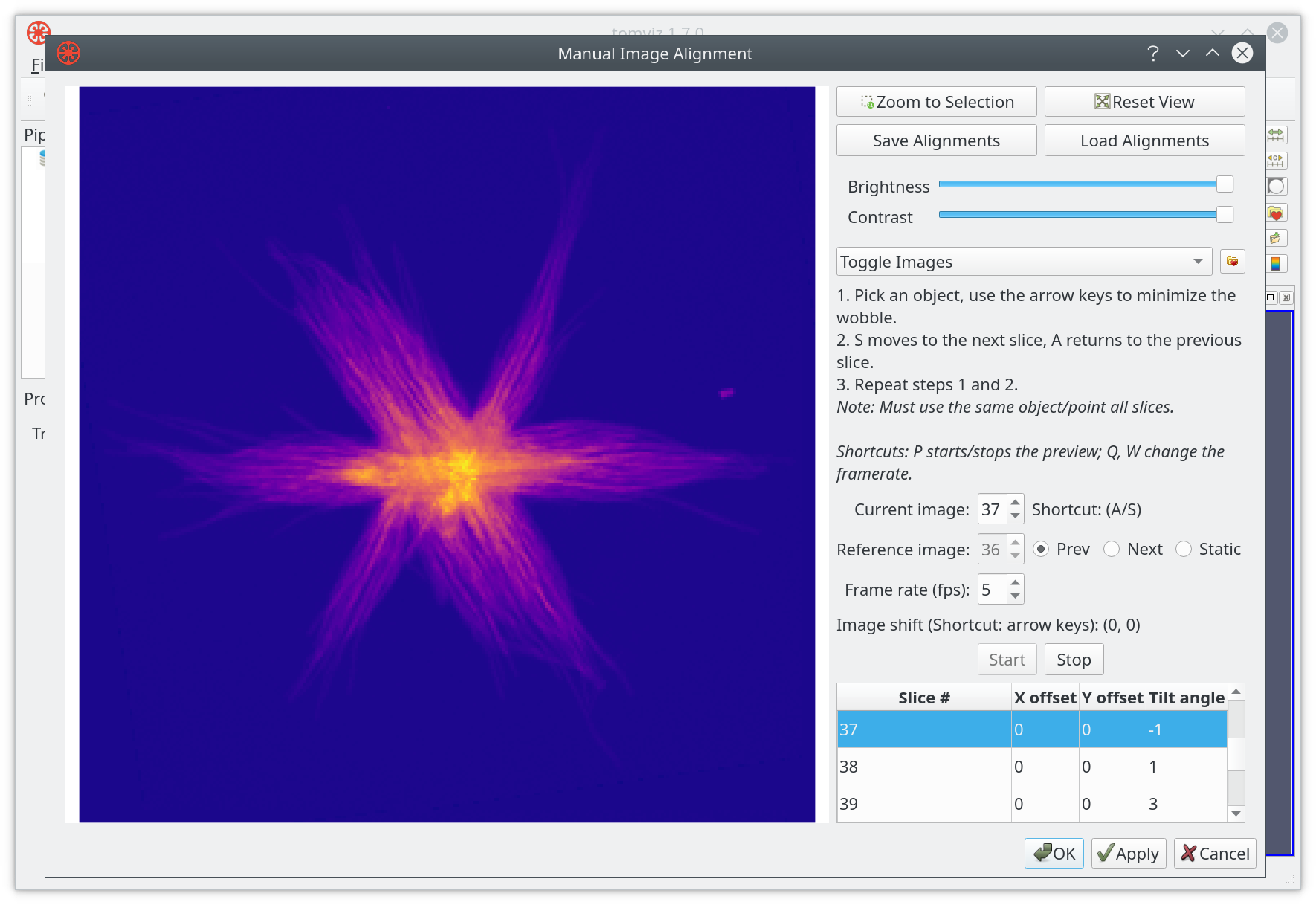
The image above shows the standard toggle mode, and below shows a typical image difference. Both modes can benefit from zooming, adjusting the brightness or the contrast. Alignment offsets can be saved to a file, or loaded from a file.
PyStackReg Image Alignment
The PyStackReg image alignment transform automatically and quickly aligns images with one another. It works well with multiple arrays (such as XRF data) because transformation matrices can be computed using one array (such as a high signal-to-noise array) and the same transformations applied to all other arrays.
First, if the data contains multiple arrays, ensure that the active array (selected in the Properties panel when the source node is clicked) is one with high signal-to-noise, as this array will be used to compute the transformation matrices.
If you wish to align all images to a particular slice, navigate to the ideal slice in a slice visualization (often a slice around 0 degrees for XRF). This slice will be automatically selected when the transform dialog opens.
Open the transform via Tomography > Alignment >
Image Alignment (Auto: PyStackReg).
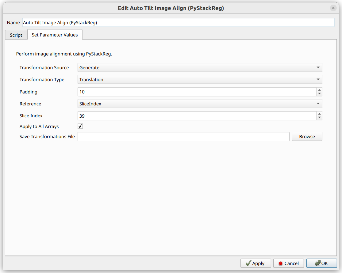
The default “Reference” is “SliceIndex”, and the slice index of the current slice visualization will automatically be selected.
The “Transformation Source” should be “Generate” to compute new transformation matrices. To reuse matrices from a previous run on a different dataset, select “Load From File”. Loading from file takes into account differences in pixel sizes, so you can apply XRF transformations to ptychography data, for example. The number of slices must match exactly, and they must correspond to the same angles.
“Transformation Type” options are detailed in the PyStackReg Documentation. All types except “Bilinear” can be applied across datasets with different pixel sizes.
“Padding” avoids image wrapping issues and is removed automatically after alignment.
“Apply to All Arrays” applies the same transformation matrices to every array.
“Save Transformations File” saves matrices and pixel sizes to NPZ format for reuse.
Tilt axis alignment
Once the images are aligned it is important to assure the tilt axis is aligned.
The tilt axis can be shifted and tilted, with reconstruction previews showing
the impact of these adjustments. Automated routines and a manual tilt axis
alignment tool are available under Tomography > Alignment.
You can choose three slices to show a preview of the reconstruction - these should be positioned on a fiducial particle ideally, with the other two on features that have contrast spread along the volume.

If the tilt axis is well aligned a fiducial marker will appear circular in the reconstruction preview. Crescent shapes normally indicate poor tilt axis alignment.
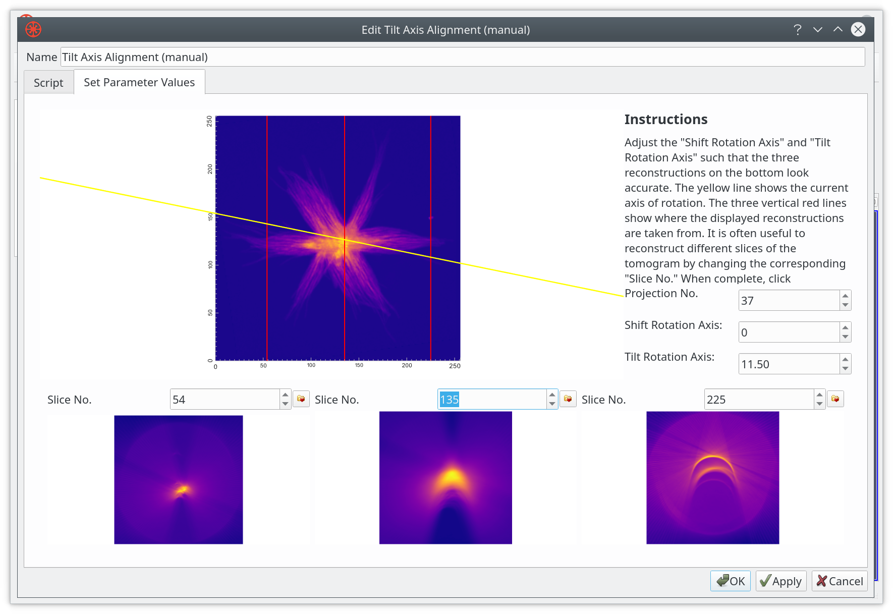
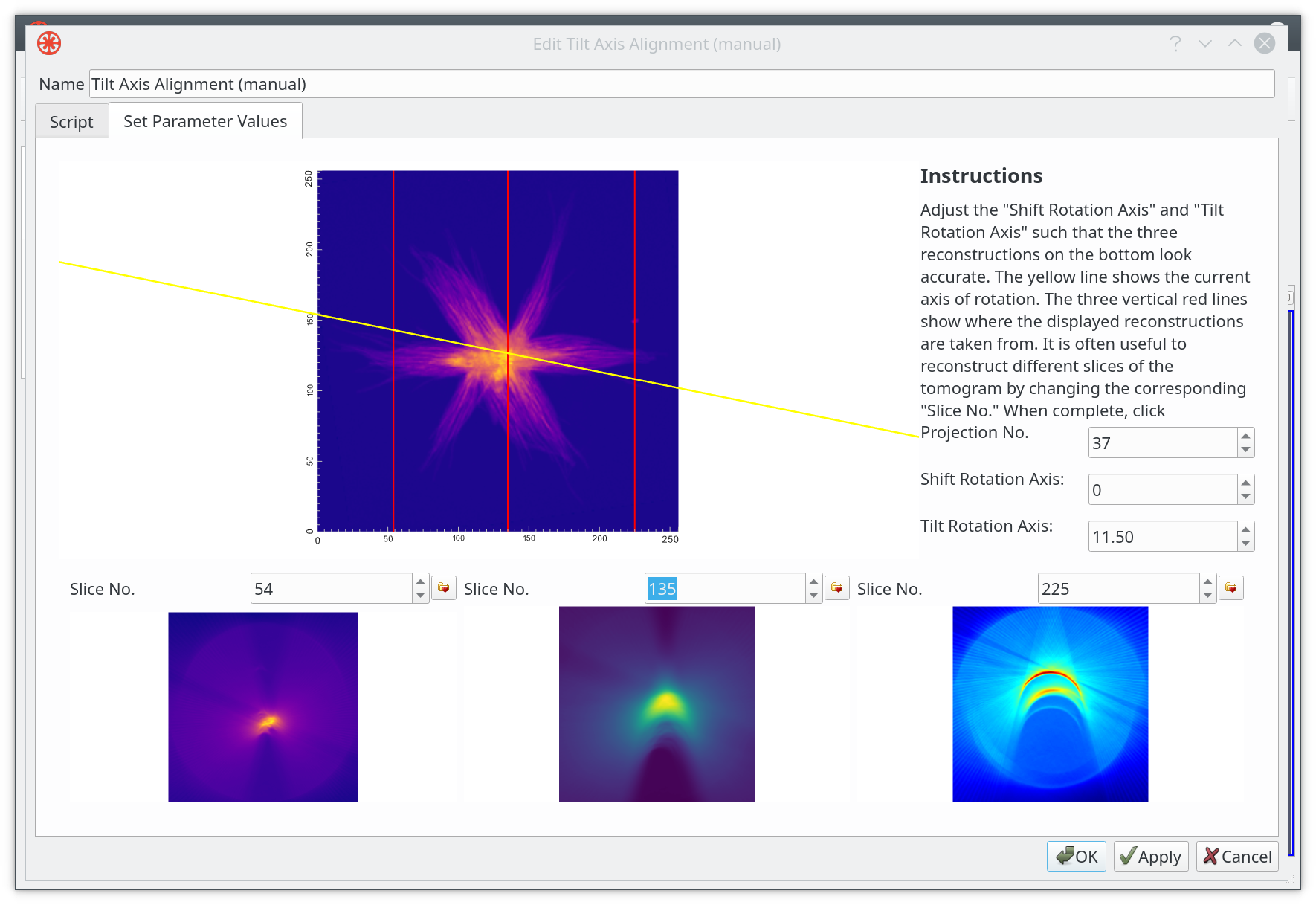
It is possible to select independent color maps for the reconstruction previews.
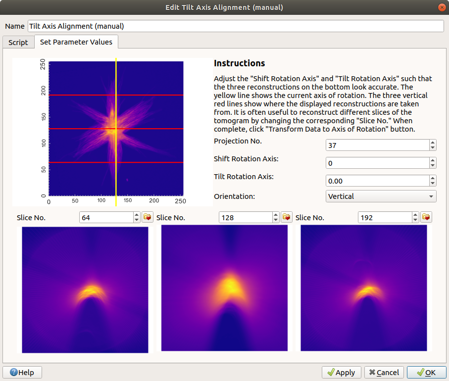
Additionally, tilt series that use a vertical axis of rotation rather than a horizontal one can be aligned by selecting “Vertical” from the “Orientation” combo box.
Auto Tilt Axis Shift Alignment
The Auto Tilt Axis Shift Alignment transform automatically shifts images to center them. It works well with multiple arrays because the shift can be computed using one high signal-to-noise array and applied to all others.
The shift can be saved to a file (with pixel size metadata) and applied to a different dataset, accounting for pixel size differences.
This should be performed after image alignment and before reconstruction.
First, ensure the active array is one with high signal-to-noise. Navigate to
Tomography > Alignment > Tilt Axis Shift Alignment (Auto).
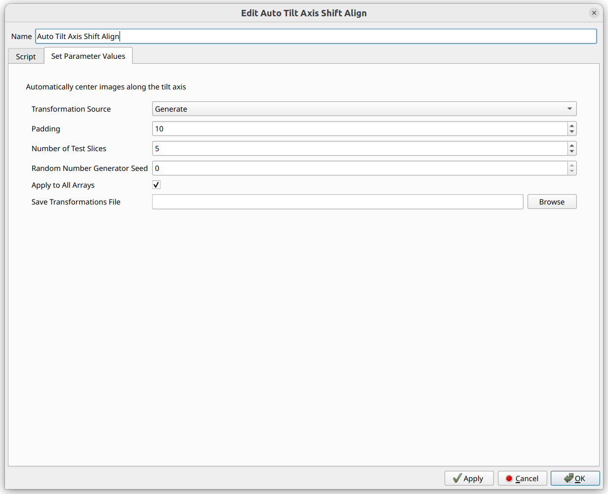
Options:
Transformation Source - “Generate” to compute new shift, or “Load From File” to reuse a saved shift
Padding - Avoids wrapping; removed automatically after alignment
Number of Test Slices - More slices may produce better results but take longer
Random Number Generator Seed - For reproducibility (default: 0)
Apply to All Arrays - Apply the same shift to every array
Save Transformations File - Save shift and pixel sizes to NPZ for reuse